Sheet metal drawing to 3D AI models your customer prints
- AI-built 3D models
- Every bend and louver
- Quality report
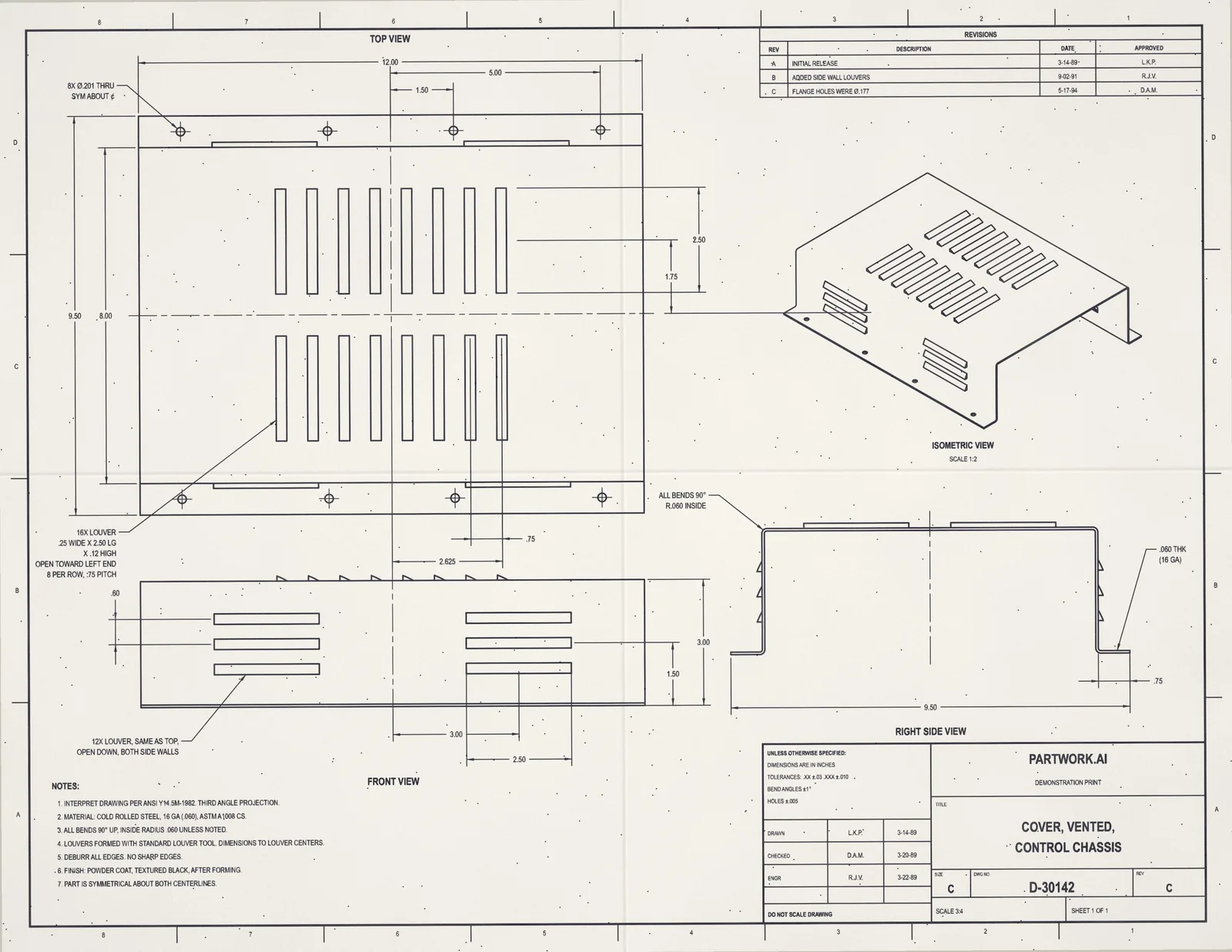
Upload a PDF or image of an engineering drawing. AI reads every view and dimension, builds a solid 3D model, and checks it back against your drawing. View your 3D model, then download the STEP and STL files and a quality report.
Does the 3D model match every callout on the print?
Yes. Each note on the drawing becomes geometry at its stated size, and the quality report checks the model against every view. Three callouts from the vented cover in the hero:
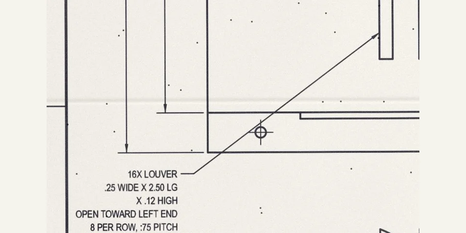 On the drawing
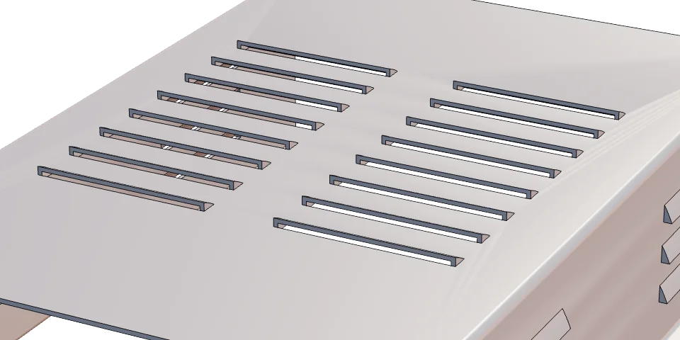 On the model
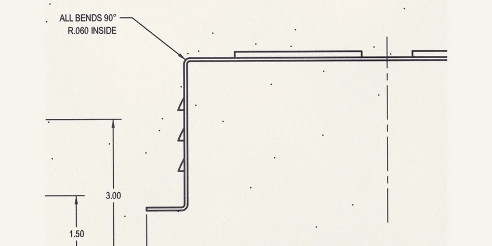
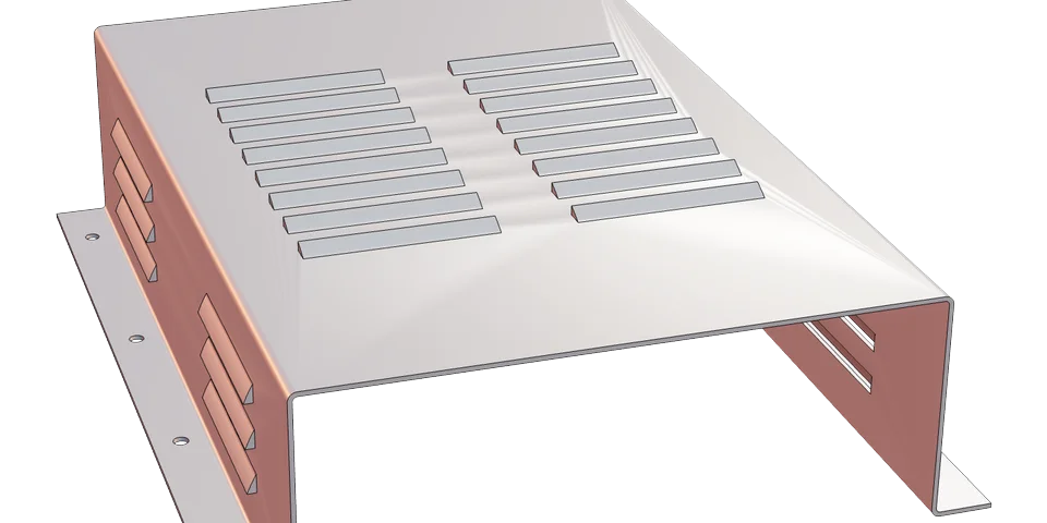
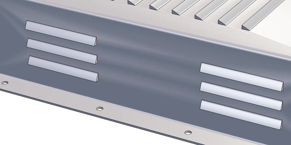
Louvers
16 louvers on top and 12 in the side walls, each at its size and opening the way the note says.
 On the drawing
 On the model
Bends and gauge
Four bends at the stated inside radius, every wall and flange at the gauge thickness.
 On the drawing
 On the model
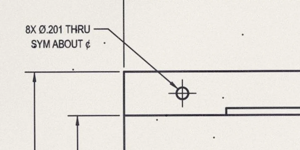
Flange holes
Eight holes through the flanges, placed from the centreline as dimensioned.
Why do fab shops redraw customer prints?
Because a PDF can’t be nested or cut. Most orders arrive as a drawing, so a programmer rebuilds every part in CAD before the laser or punch can run, and that redraw becomes the queue the whole shop waits on.
Let AI do the modelling instead: upload the print, get the formed part as a STEP in minutes, and unfold it in the software you already use. Your programmers check and nest rather than draw, so the shop scales up and takes on more work without hiring for it.
What does it build from a sheet metal drawing?
A 3D STEP of the formed part at the drawing’s gauge, with each bend at its inside radius, plus an STL and a quality report that sets every view of the drawing beside the model.
- Input
- PDF, JPG or PNG of the customer’s drawing
- Output
- STEP of the formed part, STL, quality report
- Modelled
- Thickness, bends and inside radii, flanges, louvers, holes, cutouts
- Flat pattern
- Unfold the STEP in your own CAD/CAM, with your bend allowance
- Price
- $9.99 to build; files from $29.99
- Turnaround
- Minutes, not days
- Not yet
- Freeform surfaces; drawings with missing views or dimensions
How do I get the flat pattern?
Unfold the STEP in your own sheet metal CAD or CAM. The model is a constant-thickness solid with real bend radii, so software that unfolds solids recognises the bends and builds the flat with your bend allowance or K-factor, matched to your brake and tooling.
Checking a flat by hand? The bend allowance calculator gives the allowance and deduction for any thickness, radius and angle.
How do you read a sheet metal drawing?
Read the gauge, the inside bend radius and the bend directions first, then the formed features and holes. Those few notes decide the flat size, so a model built without them is wrong before it reaches the brake.
- Gauge or thickness
- Usually in the notes or title block: "16 GA (.060)". Every wall of the part is that thickness.
- Inside bend radius
- A note such as "ALL BENDS R.060 INSIDE". It sets the bend allowance, so the flat comes out the right size.
- Bend direction and angle
- Up or down, and 90° unless a view says otherwise. The side view shows which way each flange turns.
- Outside or inside dimensions
- Flange and box sizes may be to the outside of the metal or the inside. Read which before you trust a flat.
- Formed features
- Louvers, embosses and extruded holes, called out with their size, count and which way they open.
- Holes and hardware
- Hole sizes, patterns and inserted fasteners, often dimensioned from a centreline or a bend.
How it works
- 1
Upload the customer’s print
A free check confirms we can build it; $9.99 then builds the 3D model.
- 2
We build and check it
The formed part is compared against every view of the drawing, in minutes.
- 3
Unfold and cut
Open the STEP in your sheet metal CAD or CAM, unfold it with your own bend allowance, nest and cut.
Pricing
Build your 3D Model
For $9.99 we build the part from the drawing and you look it over in our viewer, with its quality report, before you buy the CAD files.
- 3D Viewer – inspect your model in the browser
- Quality Report – every dimension checked against your drawing
- Share link – show the model to anyone, no login
Like what you see? Then download your 3D Model
Priced by what's on the drawing. Your $9.99 counts toward them.Simple
$29.99per part
Plates and brackets with a few holes.
StandardMost common
$49.99per part
Multiple views, tapped holes, pockets.
Complex
$99.99per part
Many features and tight GD&T.
A steady stream of customer prints? Ask about volume pricing.
What you get
You upload
- The customer’s PDF drawing
- A scan or photo of a paper print
- One part, or a weldment or assembly
You get
- STEP: the formed part as an editable solid, ready to unfold
- STL: for a quick look or a 3D print
- Quality report: each view of the drawing next to the model
Frequently asked questions
Can you turn a sheet metal drawing into a 3D model?
Yes. Upload the PDF or a scan and you get a STEP of the formed part: true thickness, every bend with its inside radius, flanges, louvers and holes, checked against every view of the drawing. It takes minutes, not days.
Do I get a flat pattern?
You get the formed part as a solid. Sheet metal CAD and CAM programs that unfold solids build the flat from it with your own bend allowance or K-factor, so the flat matches your brake and tooling.
Do you send DXF files?
No, the files are STEP and STL. If your nesting software needs a DXF, unfold the STEP in your CAD or CAM and export the flat from there.
We get hundreds of customer prints a year. Is there volume pricing?
Yes. Email support@partwork.ai with roughly how many drawings a month and a few typical prints, and we quote a per-part price.
Who sees our customers’ drawings?
No drafter or freelancer ever sees them. Drawings are never used to train AI, never sold, and deleted after 90 days, or sooner if you ask.
Which drawings can’t it build yet?
Freeform surfaces, and drawings with missing views or dimensions. The free check tells you before you pay.
Read more
Export-controlled drawings (ITAR/EAR) and classified drawings aren’t accepted.