Sample Engineering Drawings: Free PDFs with STEP Files
Here are five free sample engineering drawings to download as PDF: a flange plate, an angle bracket, a keyed shaft, a flanged bushing and an electronics enclosure. Each is a complete, dimensioned print in millimetres with views, notes and a title block, and each comes with the STEP file of the same part.
Which sample engineering drawings can I download?
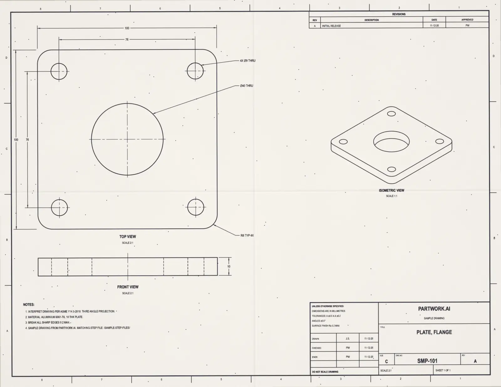
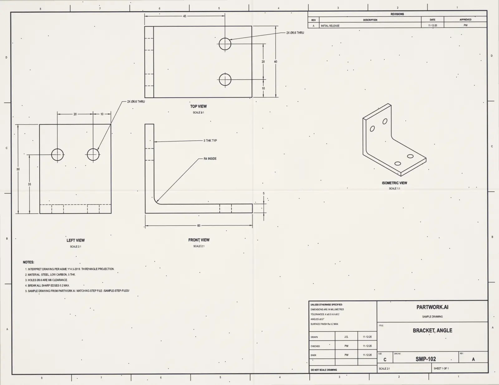
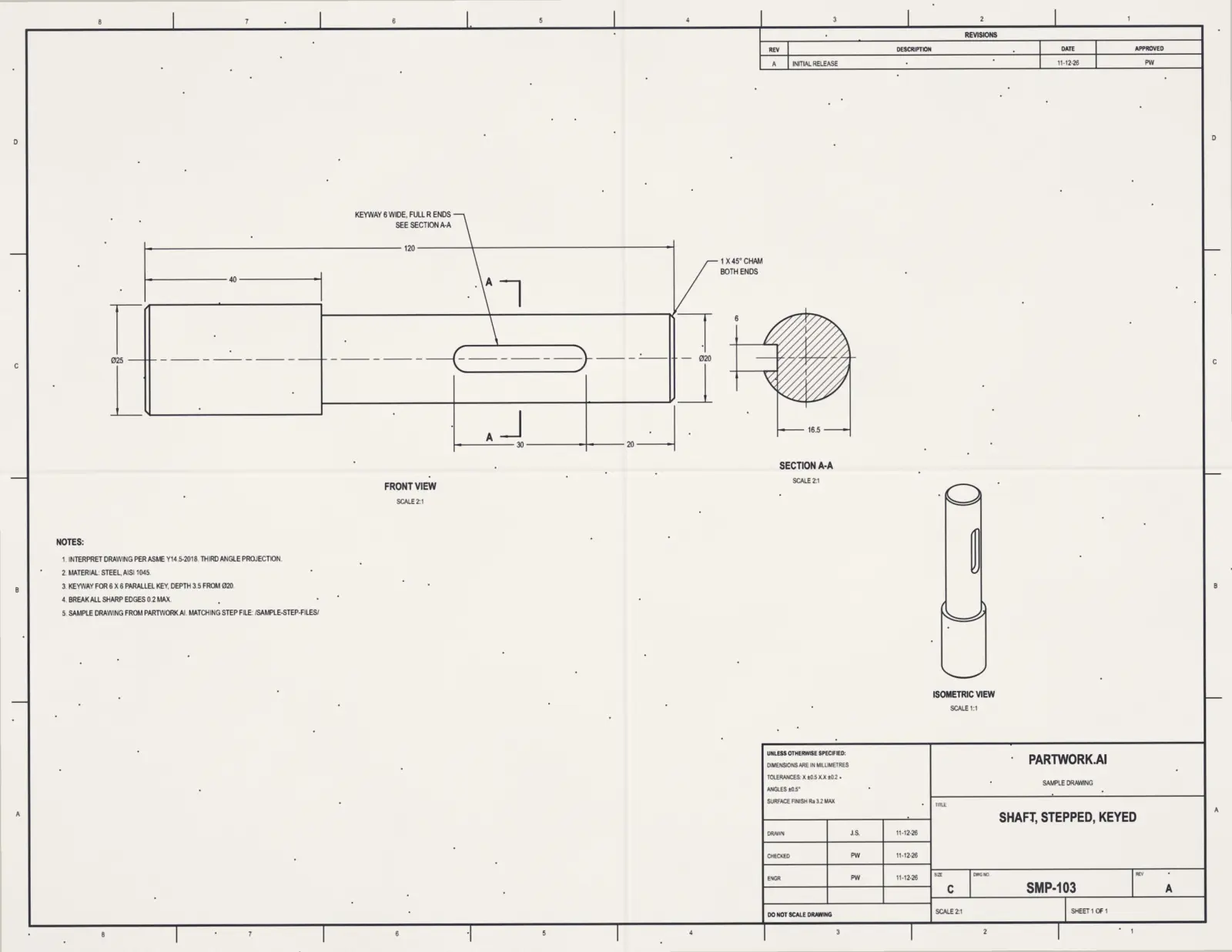
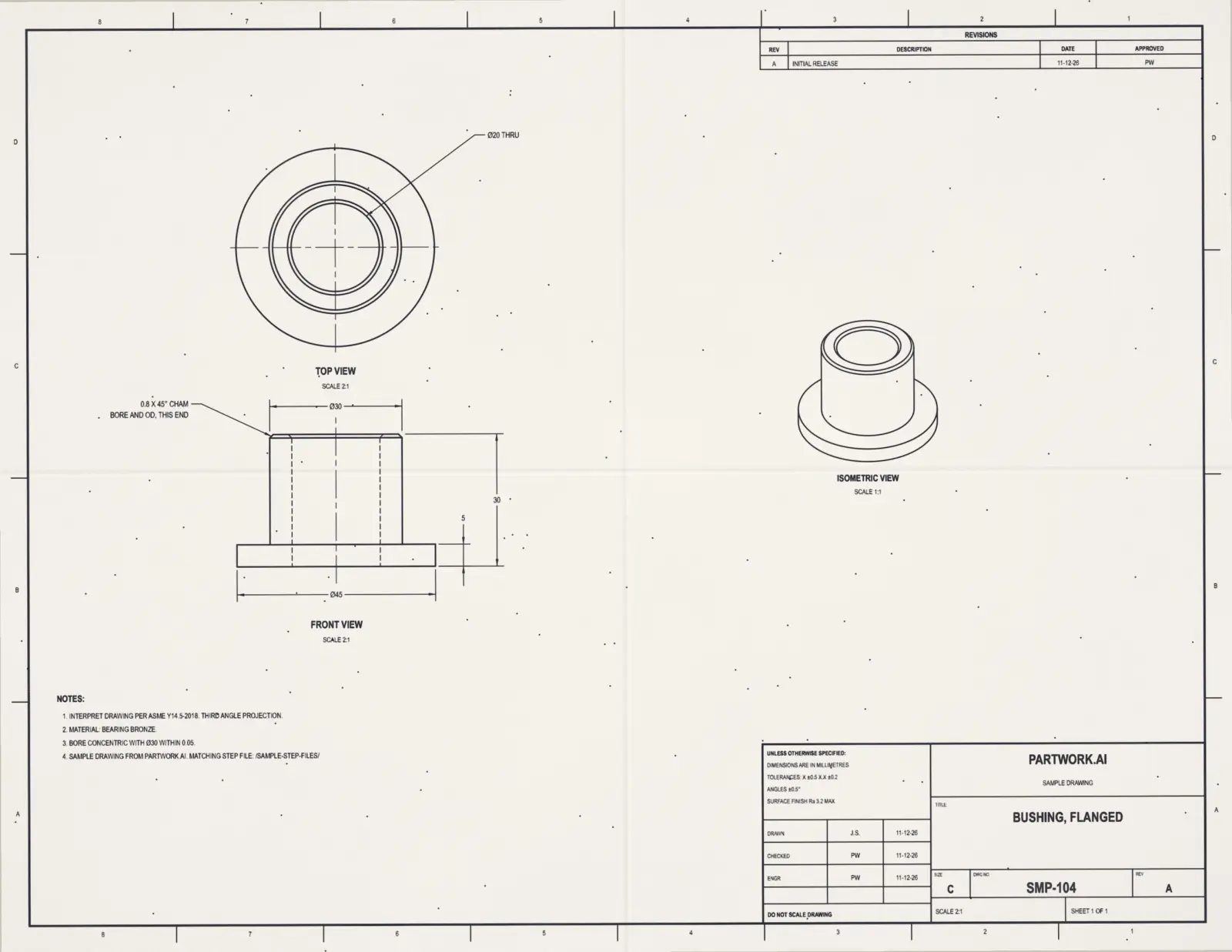
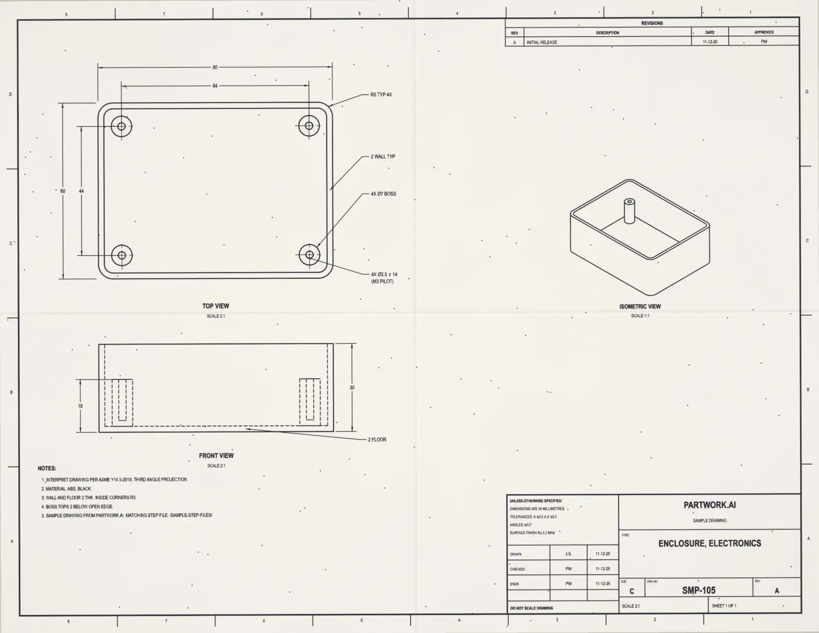
Five drawings, numbered SMP-101 to SMP-105, from a flat plate to a shelled enclosure. Each picture below is the whole sheet; click it or the PDF link for the sharp original, and take the STEP link for the 3D model the drawing describes.
What does each example drawing teach?
Each sheet uses a few drafting conventions worth knowing, so together they work as a small reading course. Start with the flange plate for the basics, then the shaft for sections and the enclosure for hidden features.
| Drawing | Views | What to look for |
|---|---|---|
| SMP-101 Flange plate | top and front views, plus an isometric | a bolt pattern dimensioned between hole centres, a 4X hole callout, a TYP corner radius and hidden lines in the front view |
| SMP-102 L-bracket | top, front and left views in third-angle projection, plus an isometric | holes on two faces located from the edges, a THK note, an inside radius and chain dimensions |
| SMP-103 Stepped shaft with keyway | a front view and section A-A, plus an isometric | a cutting-plane line, a hatched section through the keyway, diameter dimensions and a chamfer note |
| SMP-104 Flanged bushing | top and front views, plus an isometric | a turned part drawn on its axis, hidden lines for the bore, a chamfer callout and a concentricity note |
| SMP-105 Electronics enclosure | top and front views, plus an isometric | a hole-depth symbol, bosses shown in hidden lines, a wall thickness note and a TYP corner radius |
How do I read these sample drawings?
Start at the title block in the bottom right: it names the part and gives the units, scale and general tolerances. Then read the views, which are in third-angle projection, so the top view sits above the front view, and finish with the numbered notes.
A dimension with no tolerance of its own takes the block’s: a whole number such as 100 is held to ±0.5 mm, one decimal such as 6.6 to ±0.2 mm. “4X” means four of the same feature, “TYP” means the callout applies to every similar feature, and “THRU” means the hole goes through the part. The full walk-through is in how to read engineering drawings, with the symbols in engineering drawing symbols and the view layout in first vs third angle projection.
Why does each drawing come with a STEP file?
So you can check your reading against the real part. Open the STEP in a viewer, measure a feature, and it should match the number on the drawing; the model and the drawing were made from the same geometry, so they cannot disagree.
The pair is also a ready test case for anything that goes from a drawing to a model, or the other way: a CAD course exercise, a drafting check, or software that reads drawings. The same five models, with STL copies, are on sample STEP files, and open in the free online STEP viewer.
What is on every sheet besides the part?
A border with zone letters and numbers, a revision block at the top right, a title block at the bottom right and a list of notes. Real prints carry all of them, and the title block is where a shop looks first.
- Title block: part name, drawing number, revision, sheet size, scale and the people who drew and checked it.
- Tolerance block: the units and the general tolerances for any dimension without its own.
- Revision block: each change to the drawing, with a letter and a date.
- Notes: the material, the standard the drawing follows, edge breaks and anything a view cannot show.
Frequently asked questions
Where can I find sample engineering drawings?
On this page: five sample engineering drawings of simple machined and moulded parts, each a full C-size sheet with views, dimensions, notes and a title block. Each downloads as a PDF with no account, and each has the STEP file of the same part.
Are these sample drawings free to use?
Yes. They are free to download and use for learning, teaching, testing and demonstrations. The parts were modelled and drawn for this page; the names, dates and drawing numbers in the title blocks are sample entries, not a real company’s.
What units and standard do the drawings use?
Millimetres, drawn at 2:1 on a C-size sheet in third-angle projection, with a general tolerance block and notes that cite ASME Y14.5. The matching STEP files are in millimetres too, so a measurement on the model should equal the dimension on the drawing.
Why do the drawings look like old scans?
The pictures on this page are aged to look like a scanned paper print, because that is how most drawings reach a shop. The PDF downloads are the clean, sharp originals, so every line and number is crisp when printed or zoomed.
Can a drawing like these be turned into a 3D model?
Yes. A dimensioned drawing like these holds everything needed to model the part. Drawing to STEP reads a PDF, PNG or JPG of an engineering drawing and returns a 3D STEP model, checked against the drawing’s dimensions.
Have a drawing but no 3D model?
Upload it to Drawing to STEP: a PDF, PNG or JPG of an engineering drawing becomes a 3D STEP model in minutes, with files from $29.99. Scanned and faded prints work if the views and dimensions are legible; keep the drawing with the model for its tolerances and notes.